
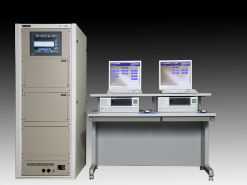
PIE-550
Plane Inspection Equipment
Discontinued Product
PIE-550 is a Surface Inspection System (WEB Inspection System) to detect any defects of a variety of web materials such as metal foils, sheet steel, paper and unwoven for sheet inspection, and glass, laminate plates, resin and food for individual sample inspection. It performs high precise inspection and user-friendly operation with Ikegami unique image processing technology.
Object:
Films, glasses, metal foils, laminate plates, resin, sheet steel, paper, unwoven, rubber and food
Contaminants, scratches, dirt, stains, uneven, wrinkles, streak, bubbles and pin hall
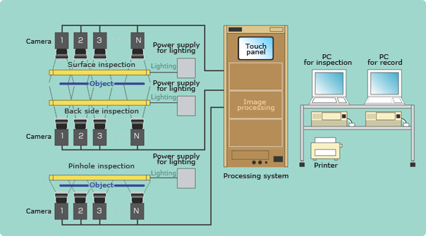
System Configuration
Flexible configuration according to the object, necessary resolution, and working width
Maximum 6 cameras per stage
Ikegami unique image processing
5 kind of defect detection algorithm
Light/Dark Spot independent parallel simultaneous processing
Ikegami unique image processing
Defect
Defects to be detected by:
(1)Detection algorithm
(2)Light/Dark Sport
(3)Length
(4)Width
(5)Area
The detection method can be set by the matrix of the above conditions.
Algorithm
Ikegami has developed 10 kinds of algorithm to detect defects.
- Tiny size defects detection(Cumulative differential)
- Small size defects detection (Differential)
- Medium size defects detection (4 points average)
- Large size defects detection (Multi points slice)
- Line-form defects detection (Density matrix)
* Each algorithm can be applied with light or darkness. Parallel simultaneous processing is possible.
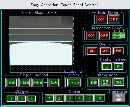
Touch Panel Control
(1) Main Power: ON/OFF
(2) Illumination Power: ON/OFF
(3) Control: Start/Stop/Interruption
(4) Display position: L/R
(5) Display method: Original/Defect image/Waveform
(6) Composition display: Normal / Composition
(7) Display mode: Movie / auto stop / manual stop
(8) Stage
(9) Camera
(10) Illumination
Fail images can be saved and displayed in real time (512x512 pixels)
Each stage of fail image can be displayed in parallel.
- Main image display
- Each stage image display
Ex. Surface, Back side and Pin hole image are displayed in parallel
- Switchable even under the inspection procedure
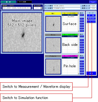
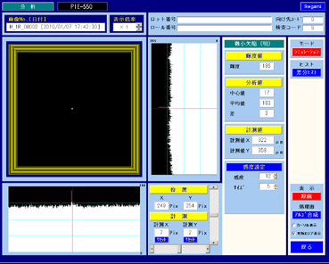
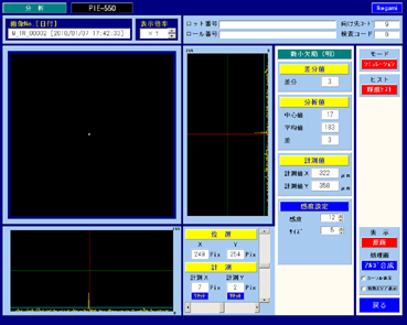
Simulation function
The recorded image which shows target defects should be loaded.
--> Set the parameter for the simulation.
--> Set the detection algorithm for the simulation.
--> The simulation result can be seen.
--> You can judge the set parameter and algorithm are suitable to detect target defects.
--> When the simulation result suits to detect the defects, the parameter and algorithm can be reflect on the settings of the system.
--> If not satisfied, you can try the simulation on the PC with different parameter and algorithm.
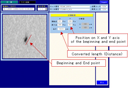
Measurement display
Clicking Beginning and End point for a target line
(Indicated by a red line)
--> Length information converted by the resolution
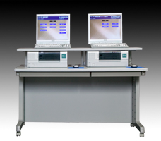
Management PC, Recording PC
- Management PC
- Parameter setting
- Display setting
- Printing setting
- Others
- Recording PC
- Defect images
- Image display even under the inspection process
- Simulation
- Waveform / Measurement display mode
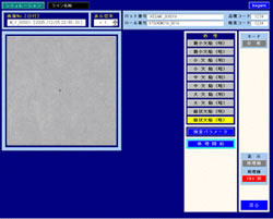
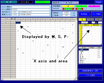
LANE display
Position information of defects at each stage can be displayed in real time
- Details information
(1) X axis
(2) Y axis
(3) Width
(4) Length
(5) Area
(6) Detection algorithm
(7) Image No.
(8) Judgement (PASS/FAIL)
| Camera | CCD line sensor camera (40MHz) Selectable between 2048, 5150 and 7450 pixels |
| Lighting | Selectable among high frequency fluorescence light, halogen lamp, metal halide lamp and etc. |
| Image processing | 10 kinds of algorithm to detect defects |
| Operation System | Exclusive PC (OS: WindowsXP) LCD display,Printer |
| Mounting | For cameras and lighting |
- Personal information is required
- Software
To download these information, personal information is required. Click the right blue button to download. :Personal information is not required.